Expert Motor Screen
Important
Check-list:
- Make sure that you have your Environment properly configured.
- That your Virtual Machine is up and ready.
- That the Python environment is set.
- That all three IOCs are running.
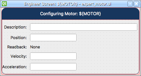
For this screen we will present detailed information to the user for the motors. Also, to ensure that we can re-use this screen in other displays, it will be necessary to use Macro Substitution that will later be replaced by the proper information for each motor.
The finished result will look like this:
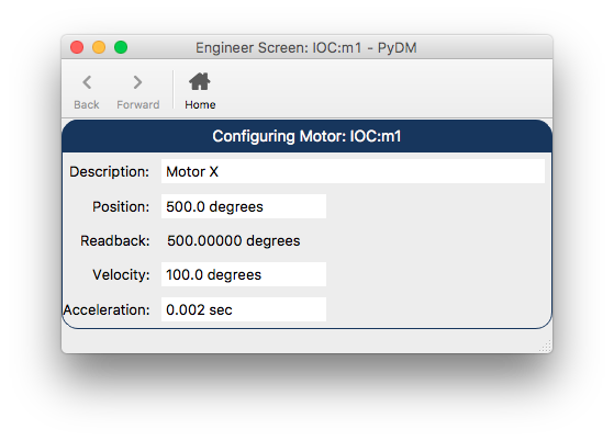
Expert Motor Screen
Step 1.
Let’s start by opening the Qt Designer and creating a new
Widget.
Step 2.
With the new form available, let’s add a
QVBoxLayoutwidget and make it fill the whole form. Let’s selectLayout Verticallyfor the Form.
Step 3.
Now that we have a layout, let’s take a look at the widgets we’ll use on this screen:
Step 3.1.
The first
QLabelwill be the title of our screen:Drag and drop a
QLabelinto the previously addedQVBoxLayout.Set the
textproperty of this label to:Configuring Motor: ${MOTOR}.Note
Macro Substitution are not something exclusive to PyDM Widgets, they can be used with any kind of widget (even the basic Qt widgets) and in any property. In this case we are using it to add the motor
PVname to the title. However, due to limitations in Qt Designer, you cannot specify a macro for a variable that is numeric-only inside Designer itself. An (unfortunate) work-around is to edit the .ui file in a text editor, and insert your macro variable into the XML that defines the display.In order to make the label look better as a title, add the following to the
stylesheetproperty:QLabel { qproperty-alignment: AlignCenter; border: 1px solid #FF17365D; border-top-left-radius: 15px; border-top-right-radius: 15px; background-color: #FF17365D; padding: 5px 0px; color: rgb(255, 255, 255); max-height: 25px; font-size: 14px; }
Step 3.2.
The second widget that we will add is a
QFrame, which will be the container of the fields in our form:Drag and drop a
QFrameinto the previously addedQVBoxLayoutunder theQLabelthat was added at Step 3.1.Set the
frameShapeproperty toStyledPanel.Set the
frameShadowproperty toRaised.In order to add some nice rounded corners to this frame, add the following to the
stylesheetproperty:QFrame#frame{ border: 1px solid #FF17365D; border-bottom-left-radius: 15px; border-bottom-right-radius: 15px; }
Step 3.3.
Now to ensure the alignment and positioning of the form content, let’s add a
QFormLayout:Drag and drop a
QFormLayoutinto the previously addedQFrame.Right-click the
QFrameand selectLayout > Layout Vertically.- This will make the QFormLayout fill the whole space of the
QFrameand make our form behave better when resizing.
- This will make the QFormLayout fill the whole space of the
Set the
frameShadowproperty toRaised.In order to add some nice rounded corners to this frame, add the following to the
stylesheetproperty:QFrame#frame{ border: 1px solid #FF17365D; border-bottom-left-radius: 15px; border-bottom-right-radius: 15px; }
Step 3.4.
Now that we have our
QFormLayoutready, it is time to start adding the form widgets. Let’s start with the first pair ofQLabelandPyDMLineEditthat will be used to edit the Description of the Motor:Drag and drop a
QLabelinto the the previously addedQFormLayout.Set the
textproperty toDescription:.Drag and drop a
PyDMLineEditinto theQFormLayoutpaying attention to add it on the right side of the previously addedQLabel.Note
The area that will match the
QLabelwill be highlighted with red borders. When that happens you will know that the widget will be placed at the expected place.Set the
channelproperty toca://${MOTOR}.DESC.Set the
displayFormatproperty toString.
Step 3.5.
Let’s now add the second pair of
QLabelandPyDMLineEditthat will be used to edit the Position of the Motor:Drag and drop a
QLabelinto the the previously addedQFormLayoutright under the previously added components.Note
The area will be highlighted with blue line. When that happens you will know that the widget will be placed at the expected place.
Set the
textproperty toPosition:.Drag and drop a
PyDMLineEditinto theQFormLayoutpaying attention to add it on the side of the previously addedQLabel.Set the
channelproperty toca://${MOTOR}.VAL.Set the
displayFormatproperty toDecimal.Select the
showUnitsproperty.Expand the
maximumSizeproperty and set theWidthproperty to150.
Step 3.6.
Let’s now add a
QLabel, and this time, aPyDMLabelthat will be used to read the Readback Position of the Motor:- Drag and drop a
QLabelinto the the previously addedQFormLayoutright under the previously added components. - Set the
textproperty toReadback:. - Drag and drop a
PyDMLabelto theQFormLayoutpaying attention to add it on the right side of the previously addedQLabel. - Set the
channelproperty toca://${MOTOR}.RBV. - Set the
displayFormatproperty toDecimal. - Select the
showUnitsproperty.
- Drag and drop a
Step 3.7.
Let’s add another
QLabelandPyDMLineEditpair that will be used to edit the Velocity of the Motor:- Drag and drop a
QLabelinto the the previously addedQFormLayoutright under the previously added components. - Set the
textproperty toVelocity:. - Drag and drop a
PyDMLineEditto theQFormLayoutpaying attention to add it on the side of the previously addedQLabel. - Set the
channelproperty toca://${MOTOR}.VELO. - Set the
displayFormatproperty toDecimal. - Select the
showUnitsproperty. - Expand the
maximumSizeproperty and set theWidthproperty to150.
- Drag and drop a
Step 3.8.
And now to the last
QLabelandPyDMLineEditpair that will be used to edit the Acceleration of the Motor:- Drag and drop a
QLabelinto the the previously addedQFormLayoutright under the previously added components. - Set the
textproperty toAcceleration:. - Drag and drop a
PyDMLineEditto theQFormLayoutpaying attention to add it on the side of the previously addedQLabel. - Set the
channelproperty toca://${MOTOR}.ACCL. - Set the
displayFormatproperty toDecimal. - Select the
showUnitsproperty. - Expand the
maximumSizeproperty and set theWidthproperty to150.
- Drag and drop a
Step 3.9.
Once all the widgets are added to the form, it is now time to adjust the layouts and make sure that everything is well-positioned and behaving nicely.
Using the
Object Inspectorat the top-right corner of the Qt Designer window, select theformLayoutobject and set the properties according to the table below:Property Value layoutTopMargin 6 layoutRightMargin 6 layoutBottomMargin 6 layoutHorizontalSpacing 10 layoutVerticalSpacing 10 layoutLabelAlignment > Horizontal AlignRight layoutLabelAlignment > Vertical AlignVCenter layoutFormAlignment > Horizontal AlignLeft layoutFormAlignment > Vertical AlignVCenter Continuing with the
Object Inspector, select theframeobject, scroll down theProperty Editoruntil the end and set the properties according to the table below:Property Value layoutLeftMargin 0 layoutTopMargin 0 layoutRightMargin 0 layoutBottomMargin 0 layoutSpacing 0 Still with the
Object Inspector, now select theverticalLayoutobject that is right under theFormobject and set the properties according to the table below:Property Value layoutSpacing 0 Finally, with the
Object Inspectorselect theFormobject set the properties according to the table below:Property Value geometry > Width 450 geometry > Height 217 layoutLeftMargin 0 layoutTopMargin 0 layoutRightMargin 0 layoutBottomMargin 0 layoutSpacing 0
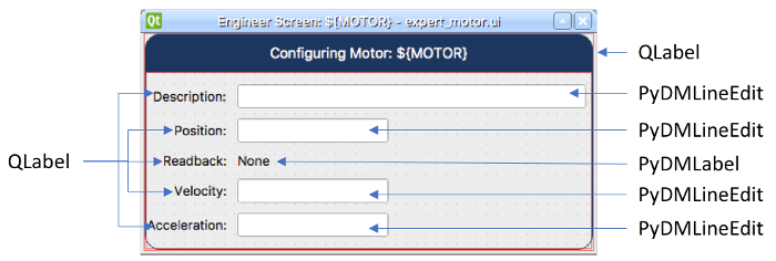
The end result will be something like this:
Step 4.
Save this file as
expert_motor.ui.Warning
For this tutorial it is important to use this file name, as it will be referenced at the other sections. If you change it please remember to also change it in the next steps when referenced.
Step 5.
Test the Expert Motor Screen:
pydm -m '{"MOTOR":"IOC:m1"}' expert_motor.ui
Note
You can download this file using this link.