The following are some simple pictures I drew to serve as a reminder of how an electromagnet works, and what the B-field looks like for a solenoid, a dipole, and a quadrupole magnet.
The first thing to think about is that a current-carrying wire generates a magnetic field that circles around the wire, and its direction of circulation depends on the direction of current flow. The applicable right-hand rule (RHR) involves pointing the thumb of your right hand in the direction of current, and then your fingers curl in the direction of B. But this assumes a "current" consisting of a flow of positive charges, and in the case of current in a wire, the flow of charge is always electrons-- so the result is backwards. Thus it's easier just to use the "left-hand rule" for normal current in a wire.
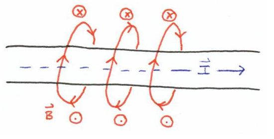
Now think about what happens when we bend the wire in to a loop, and an electron current flows around the loop in a given direction. Remember that we use DC electromagnets, so this is a steady current (not oscillating). The B-field circles around all parts of the wire with the net result that in the (2-dimensional) plane of the wire,the B-field is directed downward everywhere inside the loop's perimeter and upward everywhere outside.
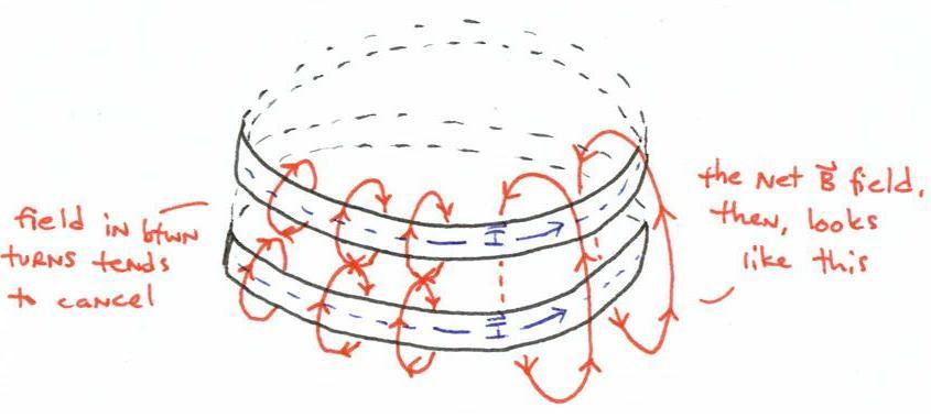
Consider two such current loops sitting one on top of the other (not touching) whose currents have the same magnitue and flow in the same direction. B-field lines are always closed, so the lines closest in to the wires will wrap around the individual turns-- but in between the turns, their magnitudes are equal and their directions are opposite-- hence they cancel, and the net field between turns is negligible (shown on the right-hand side of the drawing). Remaining field lines will wrap around both turns, and again the net field is directed downward inside the loops and upward outside.
A wire wound into a tight coil is well-approximated as a bunch of closed loops sitting on top of one another, whose currents flow in the same direction and are equal in magnitude. This makes a solenoid, whose B-field inside the winding is in the axial direction (i.e. in the direction of a central axis around which the coil is wound).
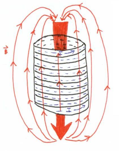
Consider that you are looking at a coil from one side. The B-field from this vantage point looks like this:
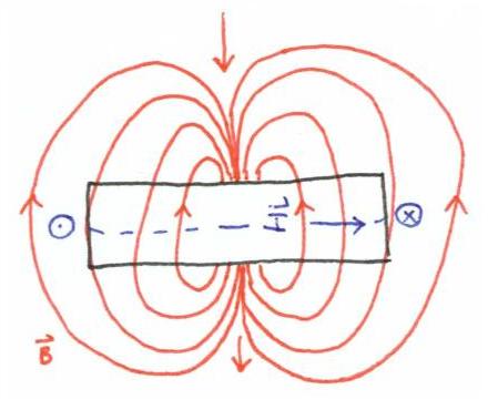
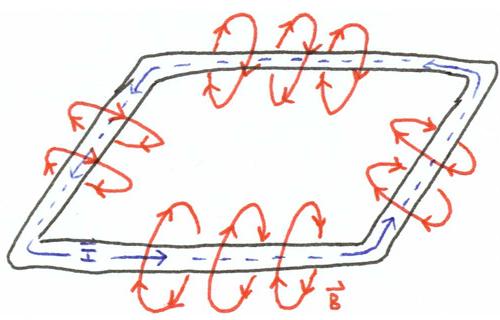
To me, this is the easiest way to draw configurations of coils that make up a dipole and a quadrupole magnet. The following drawing illustrates what the B-field looks like when you place two windings some small distance apart, with their currents flowing in the same direction. This is an illustration of a dipole magnet in air. Use the Lorentz force law and the right-hand rule to see what force a charged particle will receive when passing through this magnet. For example: consider a positron traveling into the page through this magnet. Since it's a postiron, use your right hand, and fingers curl from v (into the page) to B (downward), and the thumb points in the direction of the force, which is to the left.

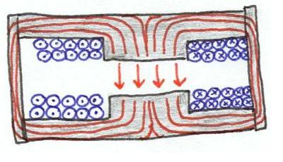
In reality, our dipole magnets aren't in air; the electromagnets used in the accelerator have iron yokes and cores which trap the B-fields, containing them for maximum strength, and forcing them across the central gap in a more uniform way. So the following drawing is a more realistic model of a dipole electromagnet, and this is how it is generally depicted in the particle accelerator physics textbooks. I found this a little confusing at first, so I hope this document will help clarify the picture for new people. This dipole is configured exactly the same as the one above, and the grey stuff surrounding it is iron.
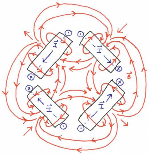
Next is a theoretical drawing of a quadrupole magnet. So the quad consists of four windings, and I've show what the magnetic field lines in a quad magnet look like. A good exercise is to mess around with the directions of the currents, and show that they have to go in a certain way in order for the quad to make the right B-field.
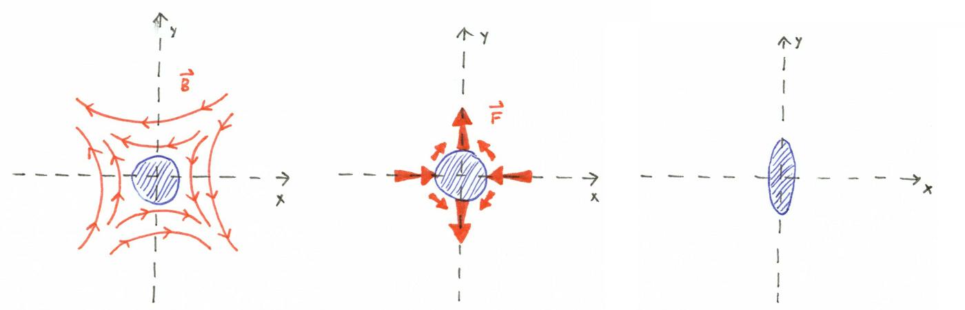
The drawing below shows what happens to a beam that passes through the middle of a quadrupole magnet. The first image shows an incoming particle bunch that is essentially round in shape, and the magnetic field it sees at the middle of the quad. The second image shows the forces that the different sides of that beam experience due to that B-field. Use the right-hand rule to verify the directions of the force (I've considered the case of a positron beam traveling into the page-- which is of course the same effect as an electron beam coming out of the page). The last image shows how the beam deforms as a result of those forces, so you can see that in this case it has "focused" in the x-plane and "defocused" in the y-plane. We call this a focusing quad or QF, since our convention is to refer to focusing/defocusing with respect to the horizontal plane. An electron beam traveling into the page would experience the opposite result-- it would squish in the vertical direction and expand in the horizontal.